

In the world of welding, efficiency and quality are paramount. There are plenty of variables you'll encounter in your pursuit of the best results while welding, but today we are talking about welding wire- specifically metal-cored wire. Using metal-cored wire in the appropriate applications can reduce costs, enhance quality, and boost productivity in welding operations. Understanding the optimal times and methods for utilizing this wire can help companies maximize its benefits. So let’s breakdown what metal cored wire actually is and what the benefits and considerations are.

Metal-cored wire is a type of welding consumable that combines the benefits of solid wire and flux-cored wire. It’s classified under AWS A5.18 as a mild steel GMAW or MIG wire, but it differs from solid wire in its structure. This is because it is a composite, tubular wire filled with materials such as iron powder, arc stabilizers, and other additional alloys that help with specific mechanical properties. The composition of materials within metal-cored wire can differ based on the specific properties and characteristics required of the filler metal.
Unlike solid wire, the core of metal-cored wire does not conduct electricity; the current travels only through the outer metal sheath. This unique construction allows metal-cored wire to maintain a higher current density at the same amperage, leading to increased productivity, excellent penetration, and a more appealing operation in axial or pulsed spray transfer modes. Due to these characteristics, metal-cored wire is not suitable for use in short circuit transfer. 

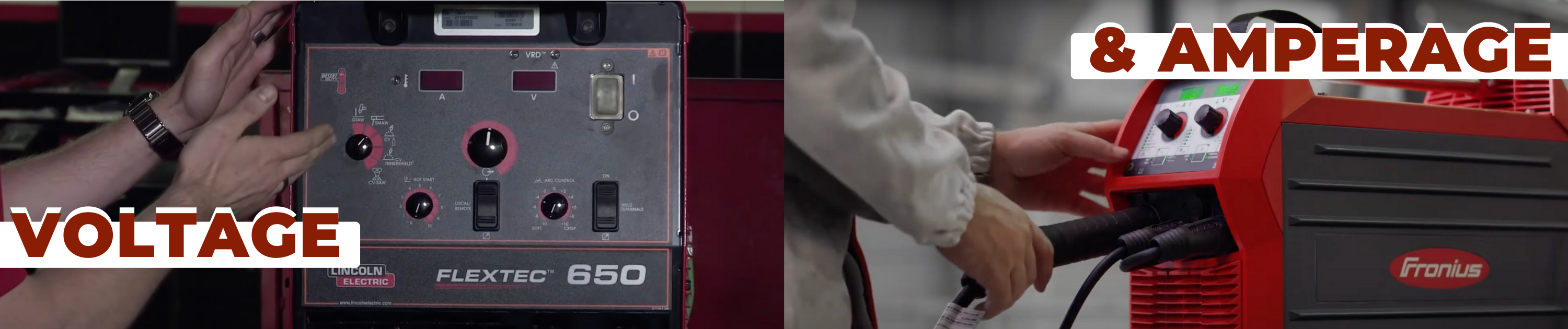
To achieve optimal results with metal-cored wire, the right shielding gas mix—typically a blend of argon and carbon dioxide—is essential. Welders must also ensure that their equipment is compatible with metal-cored wire, which may involve adjustments to voltage settings and feed speed to accommodate the wire’s unique properties. And as always, price must also be considered- when compared to solid wire, metal cored wire tends to be about 15% higher in price. However, with the right application, this 15% increase is made up by metal cored wire offering more efficiency and less re-working and finishing, which means less labor costs!
Metal cored wire is not recommended for every application, for instance it does not excel in short circuit transfer. It is also not great for sheet metal application. But industries like automotive manufacturing to heavy machinery construction, where production efficiency and weld quality are crucial, choose metal-cored wire. It is also particularly effective in robotic welding and automated applications, where its consistent feeding properties and high deposition rates can be fully utilized to up your productivity. While metal-cored wire offers numerous benefits, the cost can be higher than that of solid wire. However, the overall savings in labor, cleanup, and increased productivity often offset the initial investment. This is a material that offers significant advantages in both efficiency and quality! Its ability to improve productivity and reduce operational costs makes it a valuable option for many industrial applications.
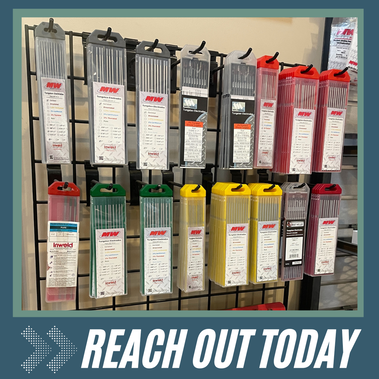
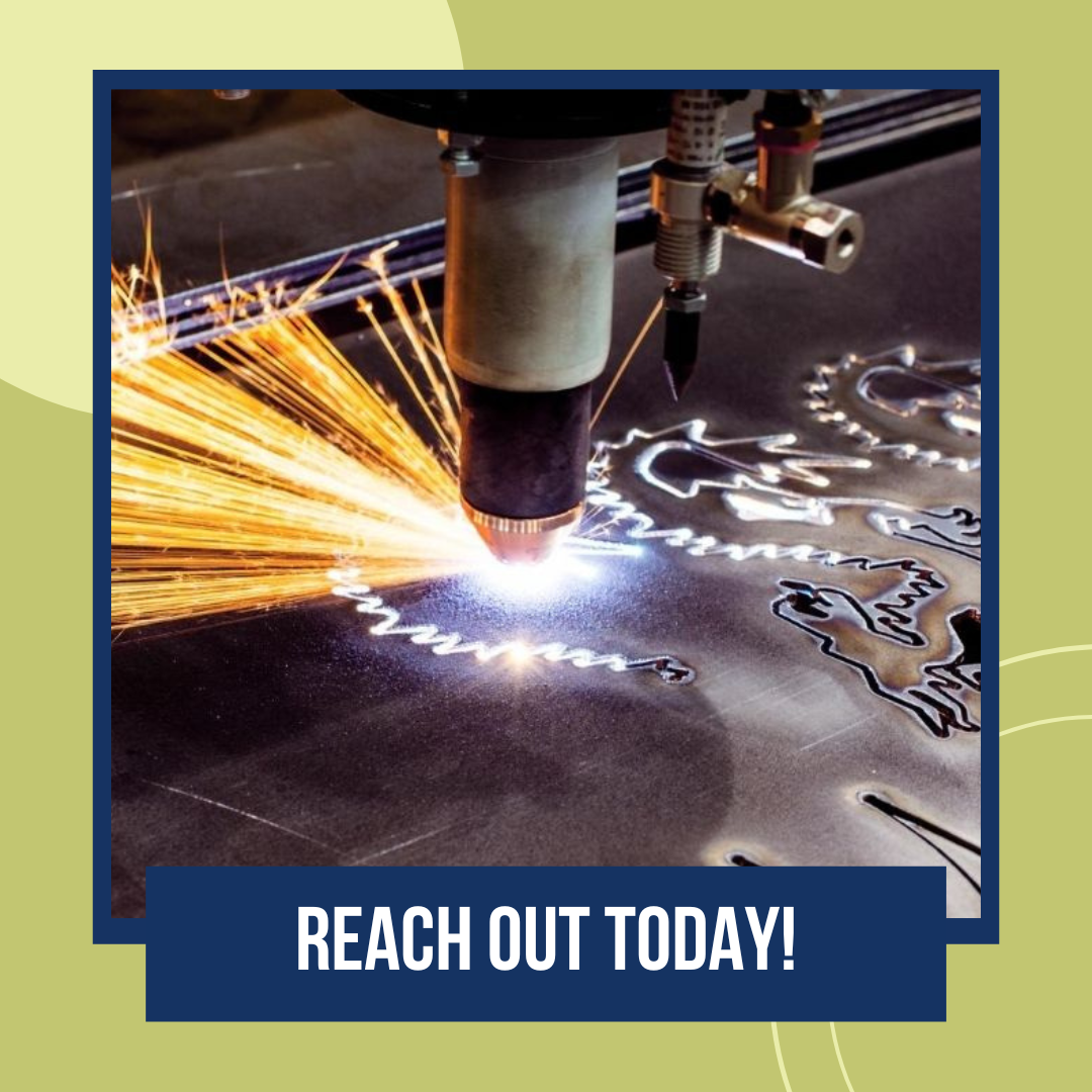
Explore the potential of metal-cored wire and consider integrating it into your welding practices! Interested in diving deeper into the world of efficient welding solutions? Just fill out the form below to reach out today! Or sign up for our free welding productivity analysis to get a tailored plan that will help your bottom line!
|
|
0 Comments
|


 RSS Feed
